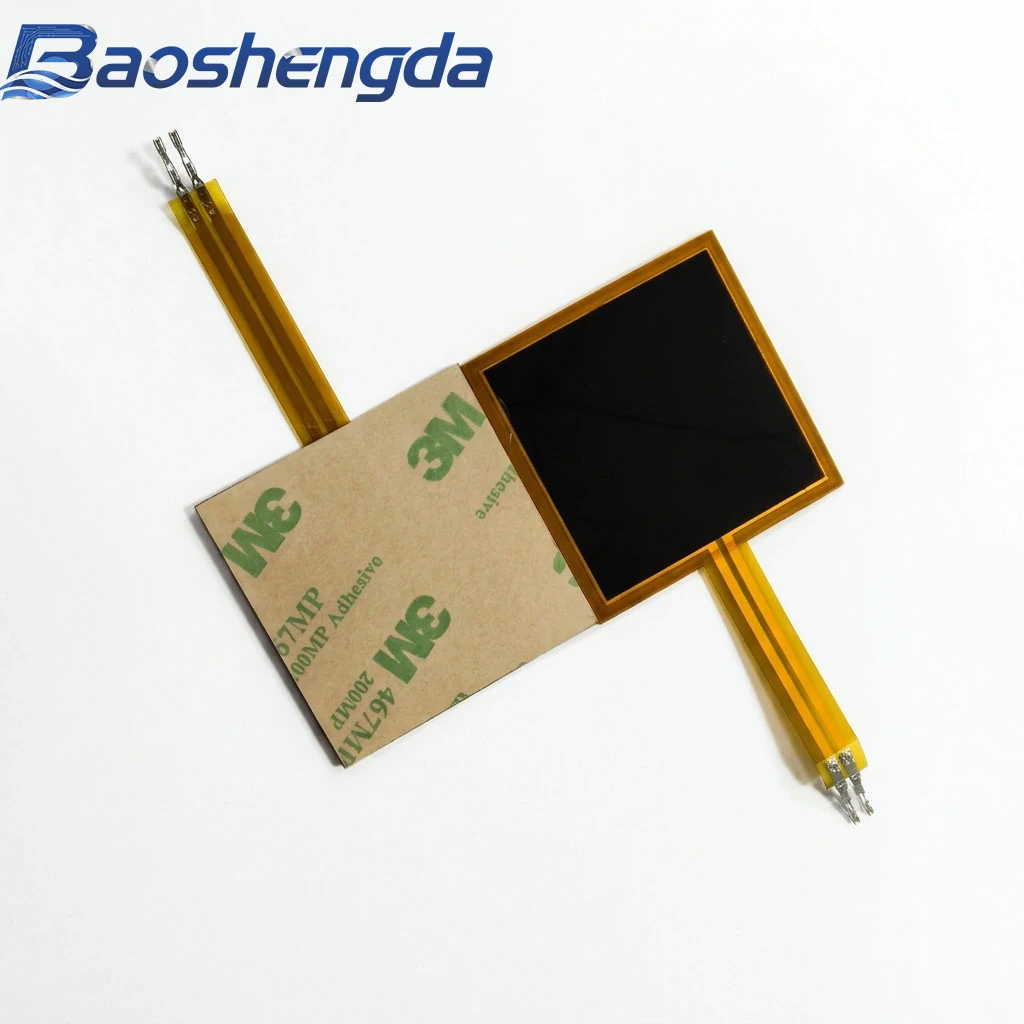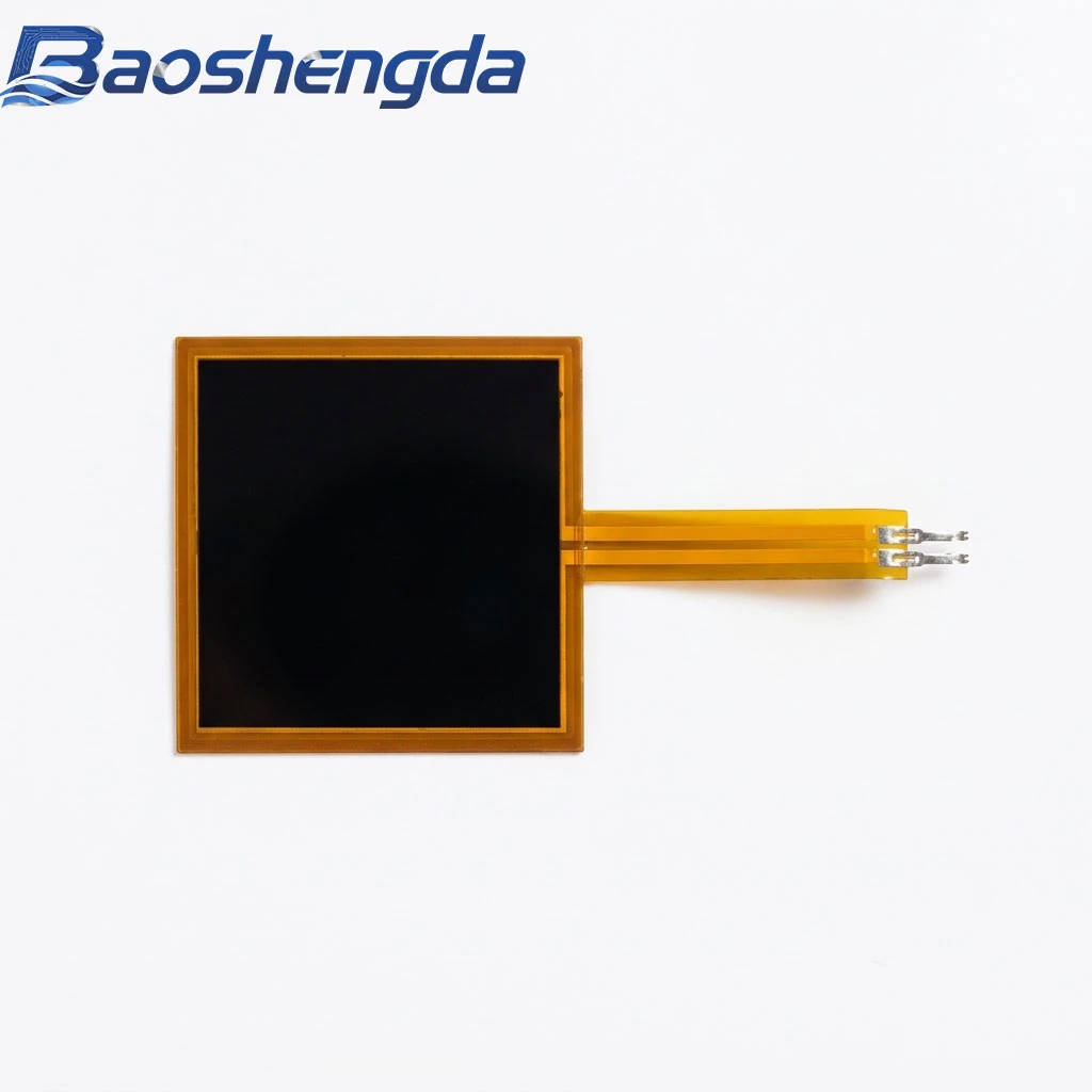
A high unloaded resistance or an over-range meter indication on an incoming FSR is not, by itself, grounds for declaring a broken circuit. First confirm the unloaded conditions and criteria for that specific model, then check meter range, terminal contact and specimen state. Where needed, record response using the loading and readout method agreed by both parties. Unloaded checks, connection checks and loaded response answer different questions; none alone replaces complete acceptance inspection.
Record meter mode, range and the actual indication first
Record the meter model, measurement mode, range, terminal locations and displayed result. Interpret OL, over-range or other indications using that meter’s instructions. Failing to obtain a finite resistance reading does not establish a physical break in the circuit. Indications from different meters or ranges cannot automatically be treated as equivalent inspection results.
Interlink’s FSR integration guide explains that its FSR resistance changes with applied force and that the starting state of its force curve can be open circuit. Its performance table also specifies unloaded and unbent conditions for stand-off resistance. These are descriptions of that manufacturer’s products; their values or states cannot be directly adopted as acceptance criteria for Baoshengda samples. The point for review is that the specimen’s state must be known before interpreting its resistance.
If an inspection document says only “normal resistance,” add the specific model, measurement conditions and agreed criteria. Where model-specific evidence is missing, retain a pending-confirmation status rather than borrowing a value for another model found online.
Record contact and assembly conditions alongside the unloaded state
Check the specimen ID, tail, terminals and appearance you are authorized to inspect, and confirm the correct measurement locations. If contact is unstable, document it and confirm the contact method first. Do not pursue a reading by clamping forcefully, piercing the film or bending it arbitrarily. A bare sensor lying flat and a sensor installed in a fixture may experience different loading even when “no weight has been added.”
Tekscan’s FlexiForce mechanical integration guide discusses the effects of loading position, contact area and mounting on its sensors’ responses. For this project, use that basis to record changes in clamping, support or preload. It does not require adopting Tekscan’s materials, actuator or installation design.
If contact, installation or specimen state cannot be held consistent, identify the difference in comparison conditions. An undamaged appearance does not establish that connections and sensing function have passed all requirements. Investigate concerns using the connection and force-transfer review, without prematurely assigning the cause to one stage.
A loaded response still needs a defined validation scope
When further checks are needed, first confirm permitted load, contact piece, loading position, support, readout circuit and reading time. Then record actual output during loading, holding and unloading. Test scope depends on the specimen and the method agreed by both parties. This article specifies no universal test force, duration or resistance threshold.
Tekscan’s FlexiForce electrical integration guide includes completed assembly, loading level and duration in calibration preparation, and distinguishes sensitivity adjustment from calibration. This supports reviewing readout under defined conditions. It does not indicate that Baoshengda samples use that circuit or that one loading action completes force calibration.
A response establishes only that a change was observed under those conditions; it cannot alone establish force accuracy, part-to-part consistency or acceptable service life. No response also requires further investigation of connection, loading and readout conditions. One test alone cannot establish sensor damage.
When handing over an incoming-inspection decision, attach the specimen ID and appearance record; meter mode, range and actual indication; unloaded, contact and assembly conditions; loading method, raw output and criteria; and items still unconfirmed. Distinguishing “pending confirmation” from “fails the agreed criterion” helps the supplier and engineering team review the same issue. Confirm force measurements with units separately using the calibration and sample inspection guidance.
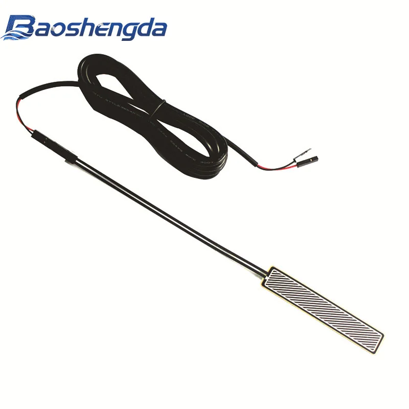
For visual identification of tails and connection ends, see the released linear-tail sample photograph used here. The photograph provides no continuity-test or batch-inspection evidence. Follow the customization and sampling process when assembling model information, drawings and inspection conditions. Records may be sent through the project inquiry page once sharing is authorized; obtain permission for private drawings and circuit details first.
This article supports project discussions. Materials, sensing range, construction and test conditions must be reviewed against your drawing and requirements.