When FSR loading and unloading curves do not coincide, first compare raw outputs at the same reference load in each loading direction, then review reading times and assembly conditions separately. A reading that changes over time under a constant load and a difference associated with loading direction should not be combined into one “hysteresis percentage.” A good fit to a single loading curve does not establish accurate force readings during unloading.
What should be recorded as load rises and falls through the same point?
Interlink’s FSR integration guide describes hysteresis as a difference in response at a given force as load increases versus decreases in a dynamic measurement. It separately defines drift as resistance changing over time under a constant static load. This supports retaining both direction and time; the guide’s model-specific values are not acceptance limits for Baoshengda samples.
Agree the permitted load range, increasing and decreasing load paths, waiting conditions at each reading point, and unloading and recovery arrangements between cycles. With the same identified specimen, assembly and readout configuration, record raw outputs as rising and falling load passes through the agreed reference points. “The same load” needs a reference loading basis confirmed for this project. Do not first calculate force using the FSR curve being evaluated and then use that force to demonstrate that the curve has no directional difference.
For each paired record, identify the cycle, reference load and direction. Retain the time the point was reached, the reading time, raw quantity and units, and the preceding loading history. The same voltage does not mean the same reference load, and the same loading-head position does not automatically mean the same force within a compliant layer. Without reference loading records, state that only the output sequence can be compared; do not report a verified force hysteresis metric.
Do waiting time and compliant layers contribute to the comparison?
Reading immediately after applying load and reading after a hold represent different observation conditions. Tekscan’s FlexiForce calibration quick-start guide calls for static calibration readings to use waiting times similar to the actual experiment, and for dynamic calibration to match the event’s time scale. This supports matching timing conditions. Its conditioning cycles, load proportions, waiting times and circuit settings are not a universal test procedure for Baoshengda samples.
If rising-load readings are taken immediately while falling-load readings follow a hold, both direction and timing have changed. Curve separation alone cannot identify the cause. Within the approved test scope, retain a separate constant-load hold segment, recording actual reference load and output over time, and review it separately from the directional pairs. Without an independent hold segment, do not attribute all curve separation to one cause.
For a seat or mattress assembly, retain contact position, cover, foam, backing, mounting and preload conditions alongside the data. Tekscan’s FlexiForce mechanical integration guide notes that compliant and rigid interface materials affect its sensors’ linearity, hysteresis and response, and discusses shear associated with material deformation and sliding. An assembled system’s difference on unloading therefore cannot be assigned entirely to the sensor without checking these conditions. This article specifies no universal loading-head material or mounting recipe.
To investigate structural effects, preserve the original assembly, then arrange comparable structural checks using a method agreed by both parties. Remounting or replacing a sensor introduces further variables that need separate identification. Overlaying two curves does not establish that foam, sensor and fixture effects have been isolated. Use the installation and force-transfer guidance to organize the relevant records.
How should results be checked and handed over after fitting a curve?
If the project requires force values with units, retain the data and loading direction used to establish the calibration relationship, then use independent records to check rising load, falling load and the project’s actual actions. Identify fitting and verification data separately. Error at the fitting points alone does not establish acceptable results on unloading or during untested actions. The project team needs to confirm any conversion or compensation method and validate it under the target conditions. “Calibrated” does not mean “hysteresis eliminated.”
A state-threshold task still needs trigger and release checks; algorithmic hysteresis is not a sensor hysteresis metric. See the action, signal and state-decision review for that distinction and synchronized records.
When handing over a sample-review conclusion, include:
- Comparison objects: specimen IDs, assembly and circuit versions, reference loading basis, and the correspondence between rising, falling and hold records.
- Timing conditions: loading sequence, reading times, recovery arrangements and any departures from the plan.
- Metric definition: raw output or converted force, the load points compared, and the denominator and calculation method for any percentage. A “hysteresis percentage” alone is incomplete.
- Verification scope: fitting versus verification data, acceptance criteria, actions covered and not covered, and causes that remain unresolved.
Results apply only to the specimens and conditions covered by those records; they do not directly establish batch consistency, service life or complete-device performance. Confirm reading and calibration preparation using the calibration and sample-inspection guidance. This article sets no universal hysteresis limit, load, loading rate or recovery time.
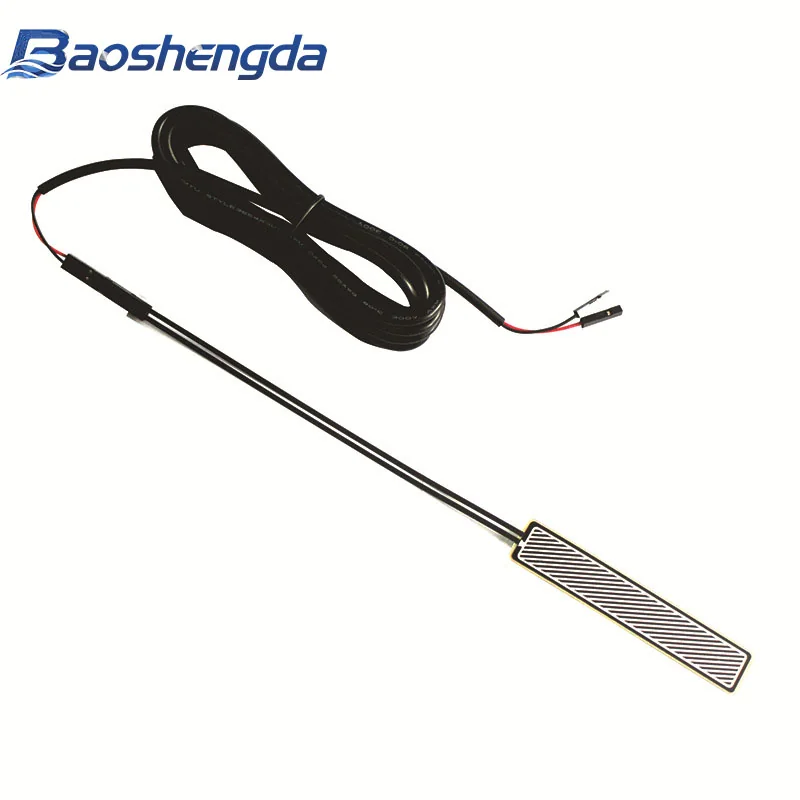
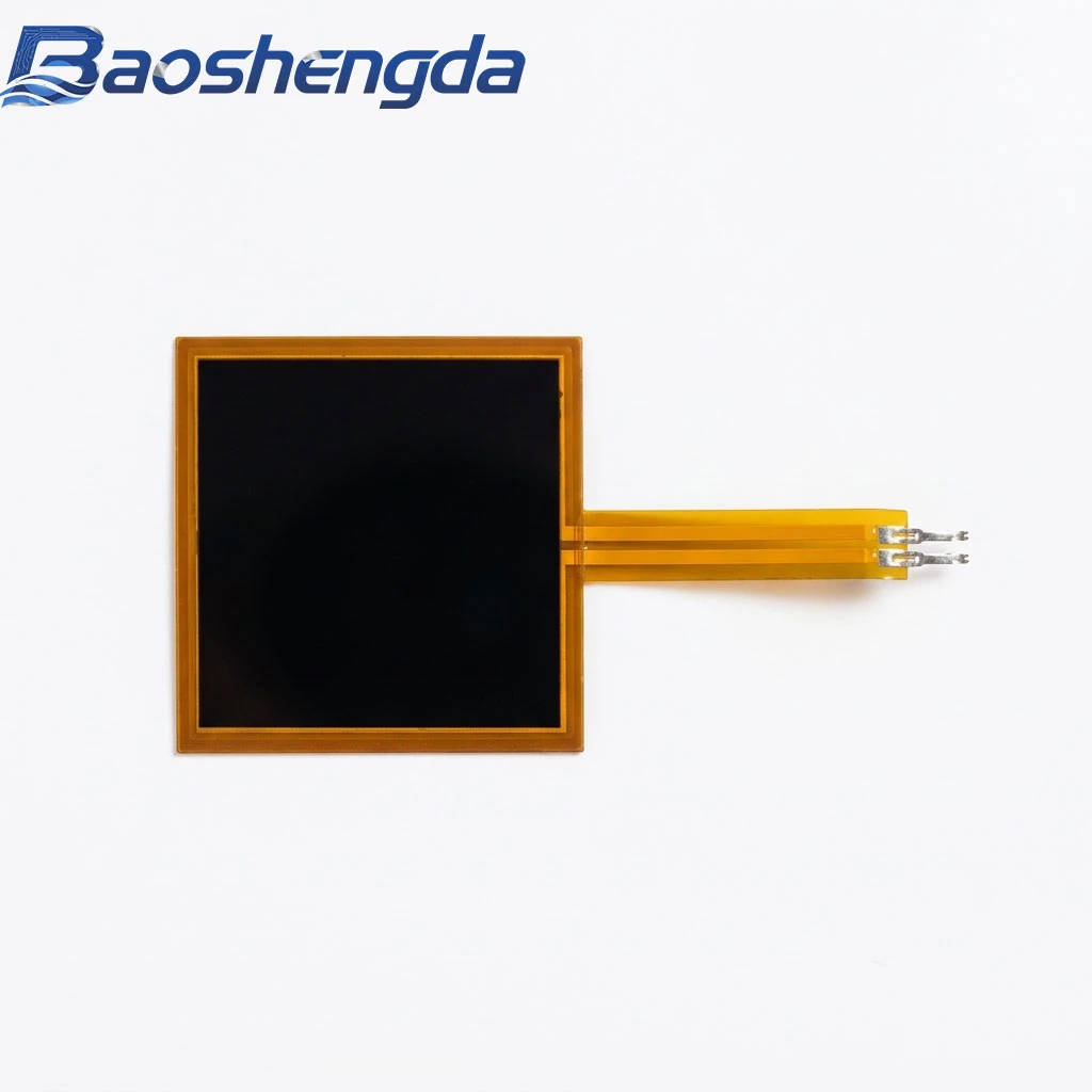
The cover shows the publicly available front and back views of square FSR samples to support discussion of shape, mounting faces and tail direction. It contains no loading curve and establishes no hysteresis performance. For a sampling discussion, organize paired records and missing reference conditions through the customization and sampling process, then submit material you are authorized to share through the project inquiry page.
This article supports project discussions. Materials, sensing range, construction and test conditions must be reviewed against your drawing and requirements.