When FSR readings hit a limit during loading, check the displayed value, raw ADC code and voltage at the ADC input separately, then review the analog front end and loading conditions. A display ceiling, the conversion range and the sensor’s response are different stages. A flat section of a curve alone cannot establish that the FSR has reached its force-range limit. Retain the raw records while the cause remains unresolved, and do not directly fit force values to clipped data.
During a seat or mattress sample review, if load continues to change while the screen value stays fixed, applying more force is not the default troubleshooting step. Stay within the test scope confirmed by both parties, identify which stage has stopped changing, and have the mechanical, circuit and software teams review their respective stages. This article provides a recording and review sequence. It does not establish saturation in any Baoshengda sample or prescribe universal voltage, resistance or force ranges.
Check raw codes before relying on a progress bar or converted value
For the same loading record, retain time, loading conditions, raw ADC codes, converted quantities and displayed values. Ask the software team to identify any maximum-value clamping, display normalization, integer truncation or replacement of error codes. “100%” may simply be a display-defined ceiling; it does not automatically represent a particular force.
If raw codes continue changing while the displayed value stops, first examine processing between raw code and display. If raw codes also remain near an endpoint, check conversion configuration and input voltage next. “First examine” describes an investigation order, not an established software or hardware fault. A screenshot without synchronized raw codes cannot distinguish these situations.
Confirm the correct channel and newly updated data are being read, and retain the actual code format, sign convention and software version. If the evidence instead points toward wiring or force transfer, consult the connection and loading review after assembly. Do not attribute every anomaly to insufficient measurement range.
Check ADC conversion range separately from permitted input limits
Have the circuit team establish how raw codes correspond to ADC input voltage for the actual device, channel mode, gain or range configuration. Measure input voltage only within the test method and permitted device conditions, identifying single-ended or differential operation, the reference point and the reading time. ADC bit depth alone does not establish the project’s maximum code, measurable voltage or measurable force.
The data-format section of TI’s ADS111x datasheet explains that inputs exceeding the conversion full scale are clipped to endpoint codes for that family. Its full-scale-range and LSB section also distinguishes conversion-range settings from analog-input voltage limits. This is an example for a particular ADC. It does not indicate that a Baoshengda design uses that chip, and its codes or voltages cannot be transferred directly to other devices. In that datasheet, FSR means Full-Scale Range, not the flexible force-sensing resistor discussed here.
If input voltage still changes while raw codes stay at the corresponding endpoint, investigate further using the actual range, configuration and measurement records. If input voltage itself has also stopped changing, inspect the preceding stage’s output. Selecting a wider conversion range does not permit applying a higher voltage to the pin. Do not probe limits by exceeding device or sample ratings during this investigation.
Limited front-end range cannot be solved only by changing a fitted curve
The circuit that converts FSR response into voltage affects the changes that can ultimately be read. Interlink’s FSR integration guide presents a voltage-divider example, explaining that the measuring resistor selects the desired force-sensitivity range while limiting current. It also notes that example curves vary with sensors and applications. Review the actual divider or amplifier configuration on this basis; reference-circuit component values are not an answer for every project.
Tekscan’s FlexiForce electrical integration guide places circuit sensitivity adjustment before calibration and explains that its design process should avoid circuit saturation before the expected maximum load. This supports checking the usable readout range first. Its devices, adjustment proportions and loading steps concern its products; they are not universal Baoshengda settings or overload-test requirements.
Within permitted conditions, have the circuit team assess actual supply, preceding-stage input and output ranges, gain and ADC configuration. If necessary, use a confirmed electrical-input check to distinguish the acquisition chain from sensor effects. If circuit output is already limited, adding ADC bits downstream or changing only the polynomial order cannot restore variations that were not acquired. If electrical headroom remains, still check contact, support and the loading process; headroom alone does not establish sensor damage.
Hand over the stages checked and the quantities not measured
Organize this round’s results into three linked groups:
- Observed behavior: the assembly and loading action under which readings hit a limit, with synchronized input voltage, raw codes, processed values and screenshots. Explicitly leave unmeasured quantities blank.
- Configuration evidence: specimen ID, readout-circuit version, actual supply, ADC model and range configuration, software processing rules and measurement method.
- Decision boundaries: stages already investigated, causes still unresolved, loads or actions not covered, and who should perform the next check.
After changing a circuit or configuration, review the target operating region under the new version, then complete calibration and sample inspection under the corresponding conditions. Two curves hitting the same ceiling do not demonstrate good part-to-part consistency. Nor does a flat section after saturation demonstrate greater accuracy or more stable force values.
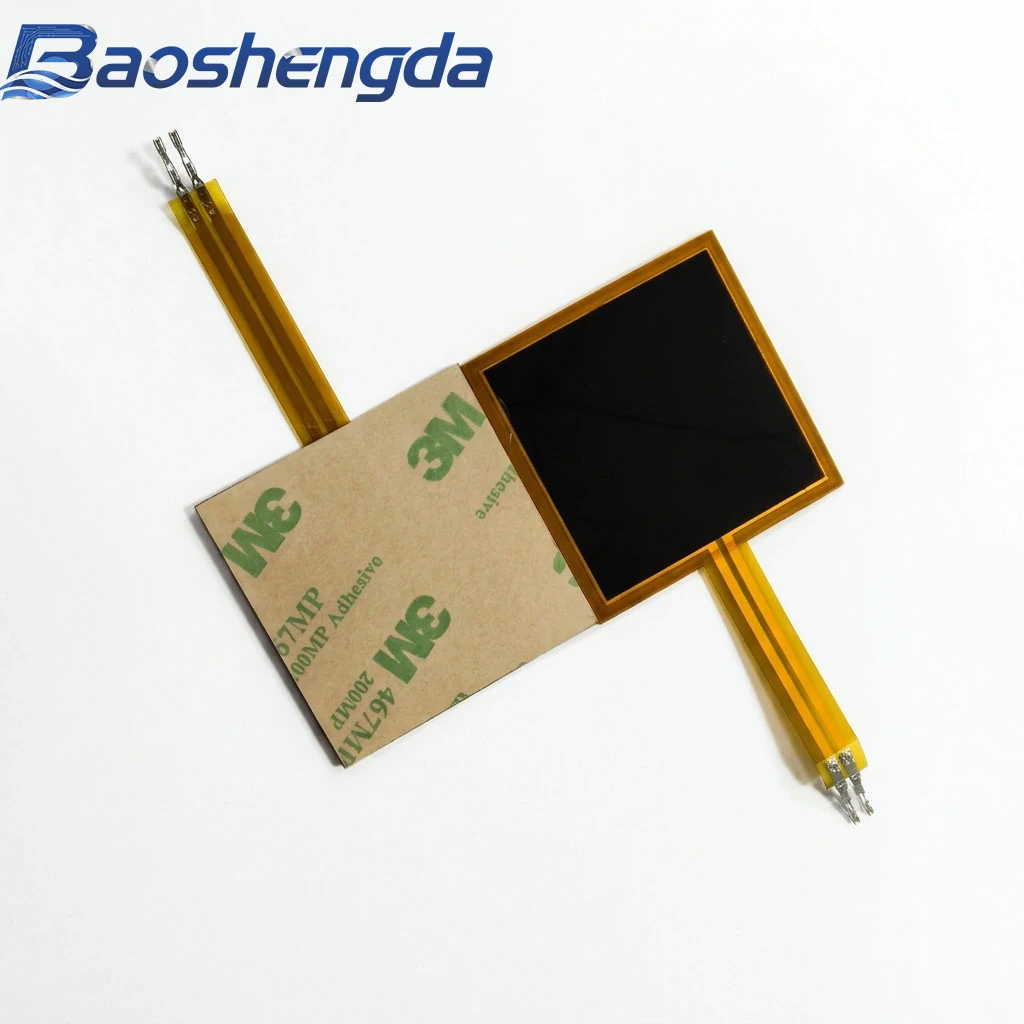
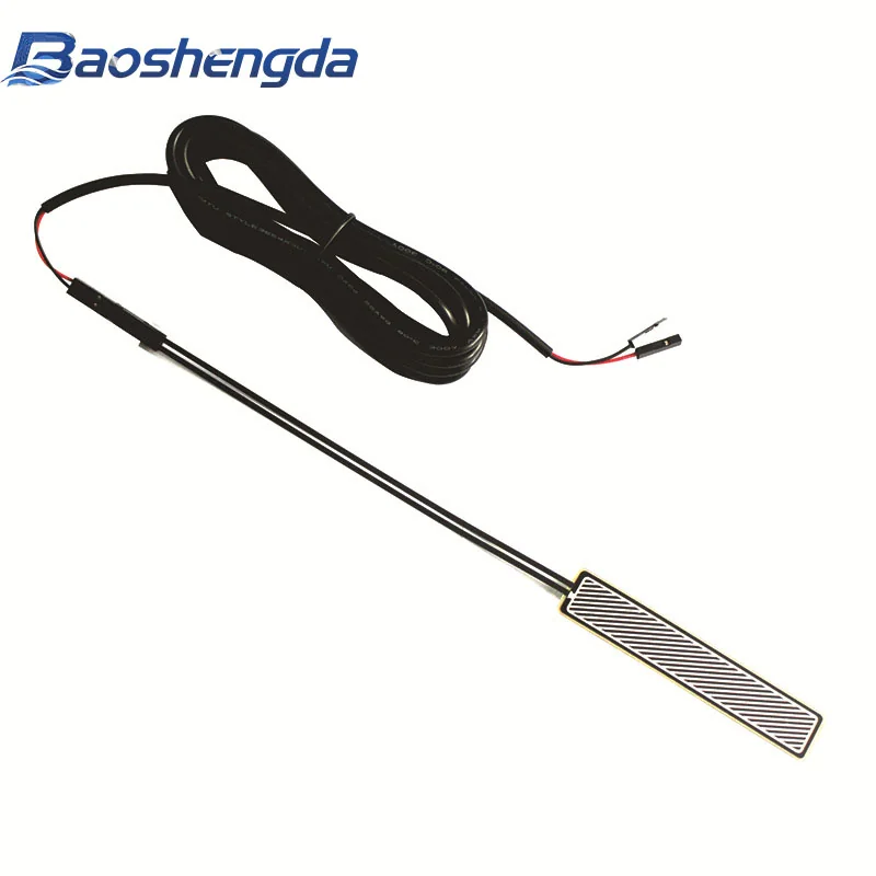
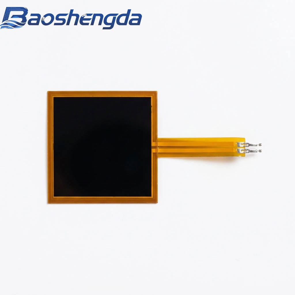
The image on this page is a publicly released square FSR product photograph for identifying the specimen and tail. It shows no readout circuit, measurement range or saturation-test result. To prepare review material, use the installation and readout guidance and customization and sampling process, then send structures, configurations and records authorized for sharing through the project inquiry page. Confirm permission to publish or share customer drawings and private circuit information first.
This article supports project discussions. Materials, sensing range, construction and test conditions must be reviewed against your drawing and requirements.