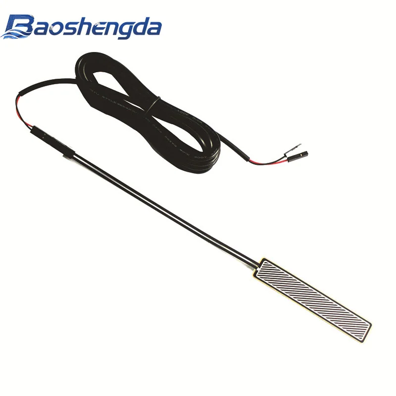
When reviewing a multipoint FSR acquisition sample, first map each installation position to its sensor ID, connection terminals and software channel. Under agreed loading conditions, record raw outputs from both the intended point and the other points. If loading one position changes several channels, examine force transfer through shared construction and acquisition-chain effects separately. A color plot alone cannot establish crosstalk, and channel count does not establish actual spatial resolution.
A Beijing science and technology platform report published on October 30 describes equipment requirements, including multichannel sensing, raised at an October 28 matchmaking event. Reviewing such samples begins with a basic check: can every recorded signal be traced to the correct physical position? This article addresses channel checks for general FSR prototypes. It does not establish that the equipment in the report has selected FSRs, that Baoshengda supplies it, or that a sample meets clinical-use requirements.
Define what a sensing position and a channel mean
On a layout drawing you have permission to share, define the viewing direction and reference edge. Identify each sensing position, sensor ID, tail direction, terminal definition, acquisition channel and display position. Specify front versus back views and drawing numbering versus software array order, so correct wiring does not produce a mirrored display.
Do not infer the number of independent channels from circular features, patterns or wire count in a photograph. Confirm how sensing positions are connected, whether they share conductors and who supplies the readout circuit against the project drawing and interface documentation.
Interlink’s FSR integration guide describes an array as a group of sensors that can be actuated and measured individually, and presents multiplexed readout methods. It helps distinguish physical layout from acquisition method. It does not establish that every Baoshengda sample shape allows each position to be read independently. Use the installation and readout notes to help confirm shape, routing and supply scope.
Why observe other points during single-position loading?
Load each position in turn using the agreed contact part, load, location and action. Retain raw outputs from that point and the other channels. Make each loading record traceable to the layout drawing rather than keeping only an image in which the intended channel has changed color.
If nearby points also change, compare the cover, foam, backing support and mounting regions to check whether they transfer load together. Tekscan’s FlexiForce mechanical integration guide discusses how contact area, loading position and compliant or rigid interface materials affect its sensors’ response. This supports including contact construction in the investigation. It is not a measured finding about adjacent responses in this project and supplies no separation distance that can be transferred directly.
Interlink’s guide also identifies crosstalk caused by actuation of another sensing position on the same substrate. Within the approved test scope, consider comparing a sensor on independent support with the complete stack, while the circuit team checks the acquisition chain. Record structural and readout conditions separately before attributing every adjacent change to the sensor or a particular fault.
How does a sequential scan relate readings to time?
If positions connect to the same acquisition chain in turn, record channel order, the arrangement between switching and taking a reading, and the actual update cadence of each channel. Refreshing a set of values together on screen does not establish simultaneous sampling at every position. Interpret rapidly changing actions against the individual channel timestamps.
Analog Devices’ analysis of input settling time in multichannel data acquisition explains residual charge and settling after switching inputs in the multiplexed systems it discusses. Insufficient settling can allow the previous input to affect the current sample. This explains a particular signal-chain issue; it does not establish that your FSR circuit has crosstalk.
The circuit team should confirm switching and sampling arrangements against the actual components, input conditions and target error, then verify them using agreed electrical-input checks and sample-loading records. This article specifies no universal waiting time, sampling rate or component value. Duration and signal records without channel identity cannot reconstruct changes at each position. Once channel mapping is clear, review thresholds using the synchronized action, signal and decision record.
Make each handoff record traceable to its physical position
Consider including the following with the drawing for a multipoint sample. The project parties still need to agree on test methods and acceptance criteria:
- Mapping: viewing direction, position numbers, sample IDs, terminal definitions, acquisition channels and display positions, with drawing and configuration versions.
- Loading conditions: the position being loaded, contact part, load, support, cover and preload; state whether other positions also receive load.
- Readout: channel order, switching and reading arrangements, per-channel times, raw quantities and units; identify filtering, calibration and display processing separately.
- Changes and conclusions: actual neighboring-channel records, structural and circuit conditions already checked, causes not yet distinguished, and actions or positions outside the test scope.
Distinguish regions between directly measured points from the actual measurement positions. Identify software interpolation, normalization and color scaling as well. Display smoothness is not spatial resolution or measured accuracy. If force values in engineering units or a pressure distribution are required, separately confirm calibration, area definitions and validation scope. See the calibration and sample inspection notes.
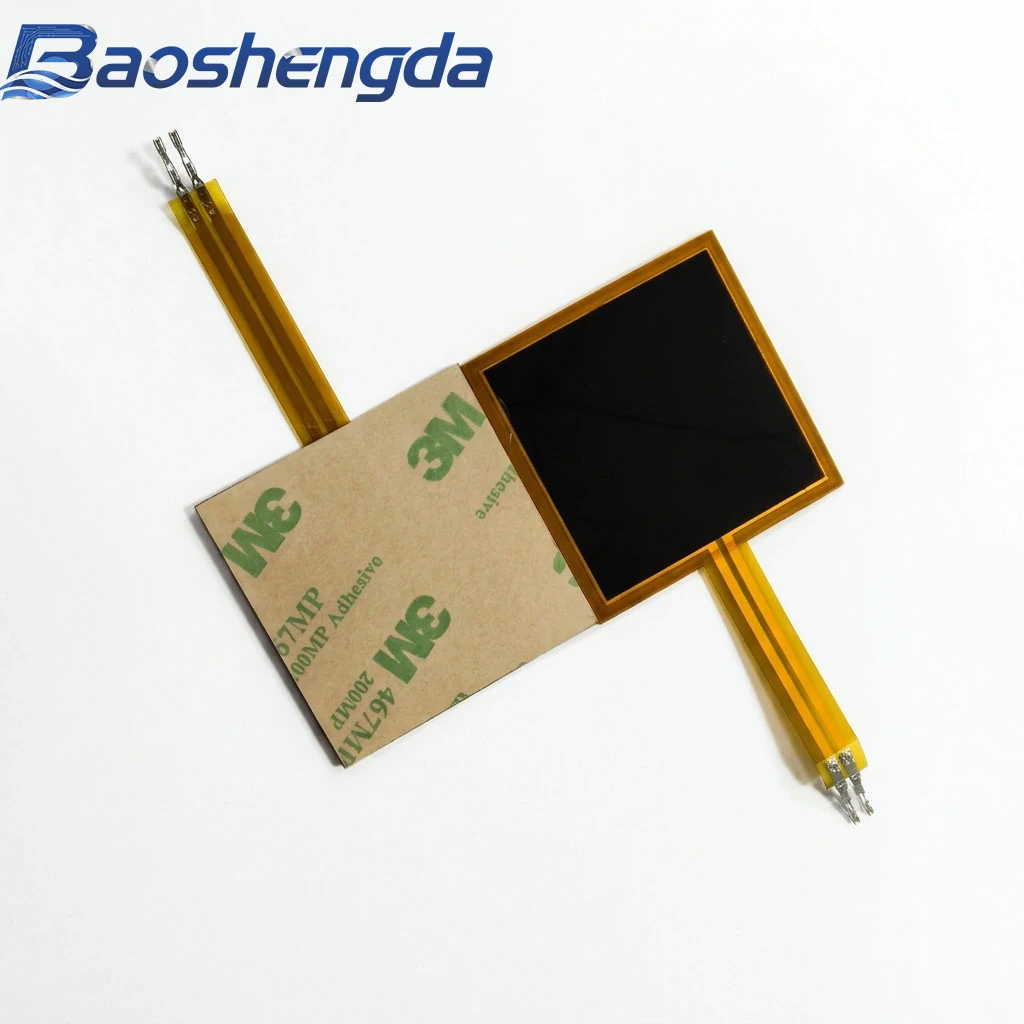
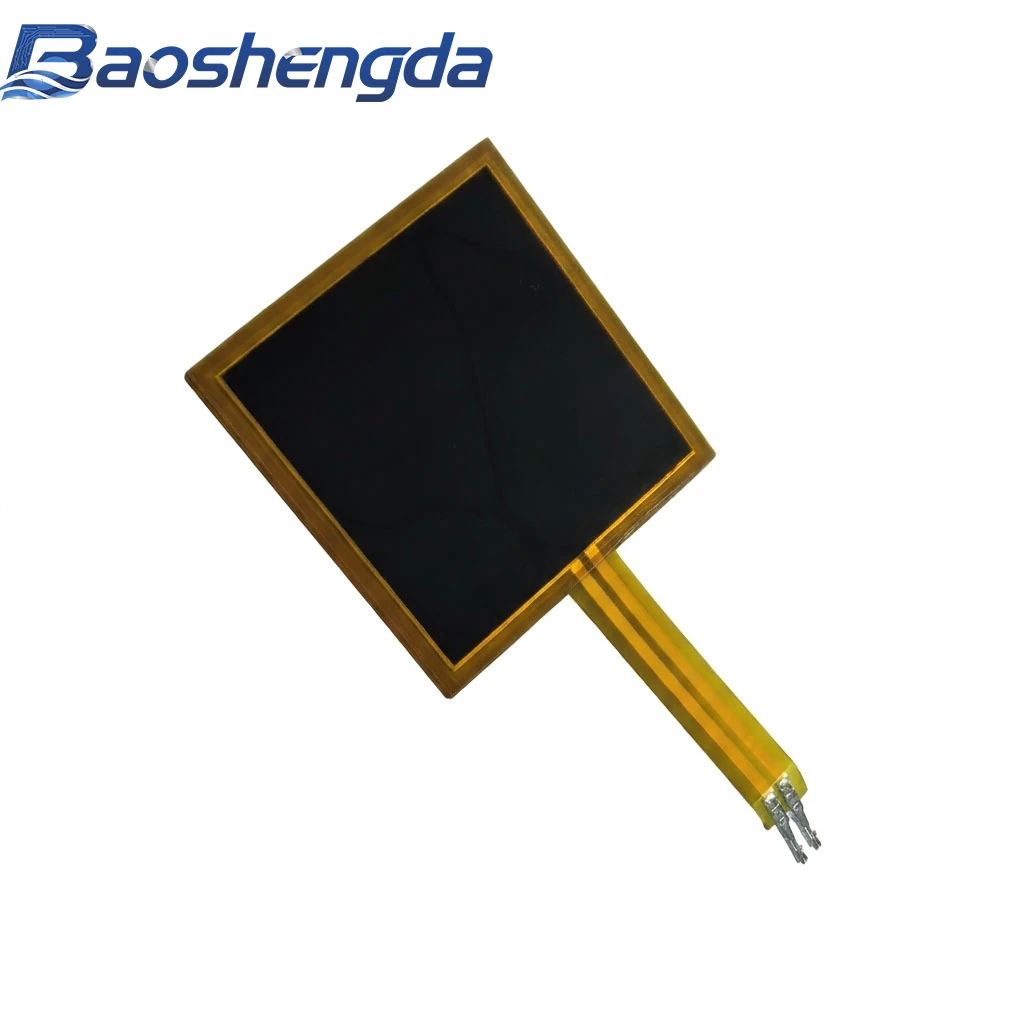
You can also use this mapping record during a seating layout review. The cover is a public square FSR sample photograph, used only as an appearance reference for the sensor and tail direction. It is not a multichannel wiring diagram or crosstalk test result. Before sampling, use the customization and sampling process to organize the layout drawing, interface and checks for this review, then submit information through the project inquiry page. Confirm permission before sharing unreleased customer drawings.
This article supports project discussions. Materials, sensing range, construction and test conditions must be reviewed against your drawing and requirements.